Case Editor
The Case Editor is the primary means to graphically create a case in Case Management Model and Notation (CMMN) using simple drag-and-drop commands.
User Interface
The Case Editor interface is roughly divided into four areas:
-
The menu bar on top, just below the navigation bar
-
The palette on the left side
-
The canvas in the middle
-
The attribute bar on the right side
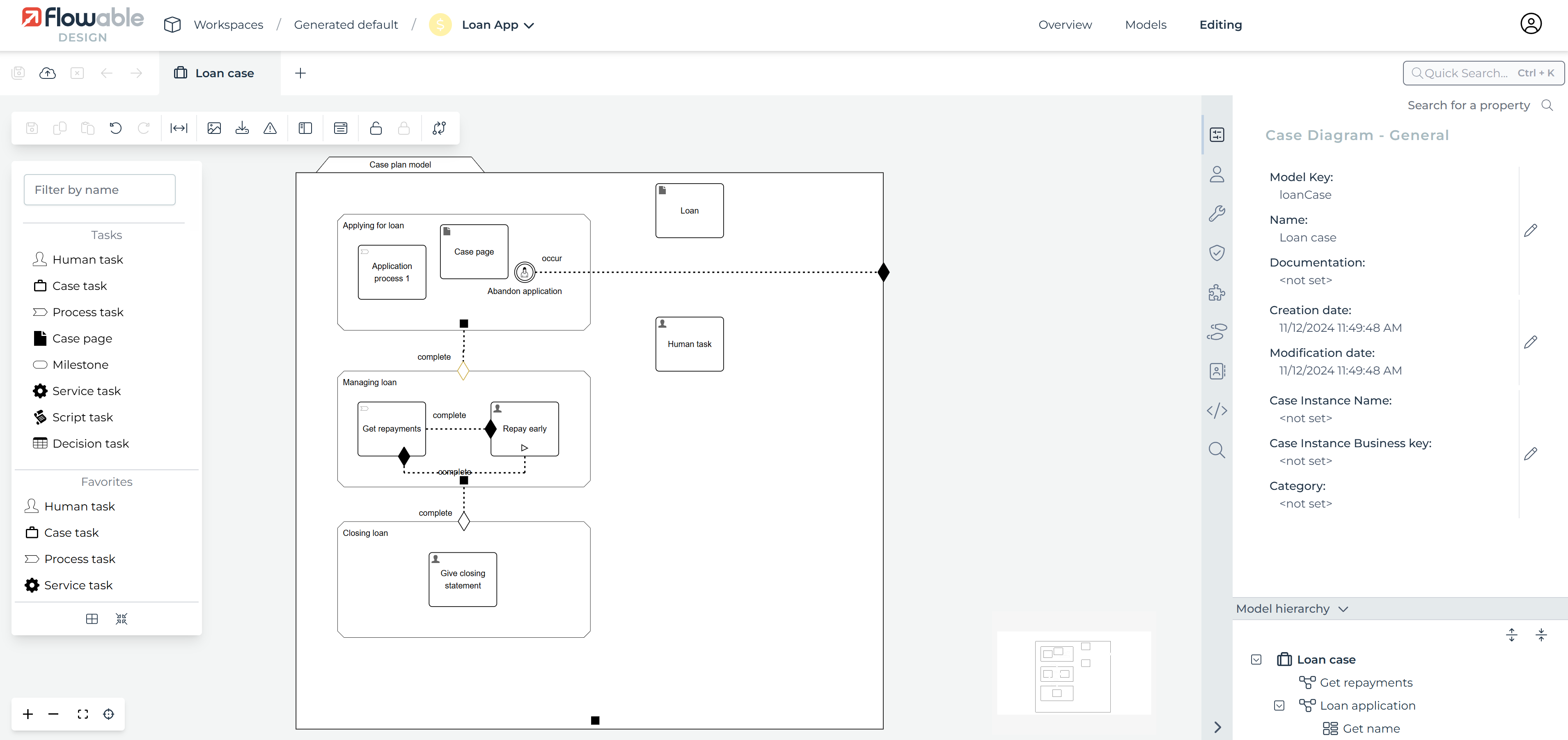
The following sub-chapters describe each area in detail.
Menu Bar
The menu bar offers a number of actions, some of them only affecting the currently opened model while others have a more global impact.

| Group | Icon | Description |
|---|---|---|
| Save | Saves the currently opened model. | |
| Saves all opened models. | ||
| Validate | Validates the currently opened model. | |
| Edit | Copy the selected element. | |
| Pastes the contents of the clipboard. | ||
| Cuts the currently selected element. | ||
| Protocol | Undoes the previous action. | |
| Redoes the most current action. | ||
| Layout | Activates spacer tool. | |
| Locking | Locks the current model, see model locking | |
| Unlocks the current model to allow all user to get the lock. | ||
| Model | Opens the Data Model Viewer. | |
| Configure data contracts with data dictionaries. | ||
| Opens the Revision Editor, see model versioning. | ||
| Searches for an attribute value within the currently opened model. | ||
| Opens the variable view showing the variables created and used in the model. | ||
| Export | Exports the currently opened model in the saved state. | |
| Exports the currently opened model in the saved state as a picture. | ||
| Publish | Publish an app, see publishing apps. |
Drawing Criteria
Often you want to add entry or exit criteria to tasks or other case item. To do this, drag an entry or exit criterion shape from the Sentries group of elements and drop it on the task or item that needs to react to the sentry. While you are dragging the shape and hover over a task or item, the items outline changes to a green to indicate it is an allowed target for the criterion. Drop the criterion shape and a diamond representation of the sentry is added to the task or item.
If the entry or exit criterion is to be defined as an expression, the Condition attribute of the criterion can be used to enter the expression. You can also connect the criterion to another case item by clicking on the criterion diamond shape and access the connector tool from the item’s tools to drag a connection.
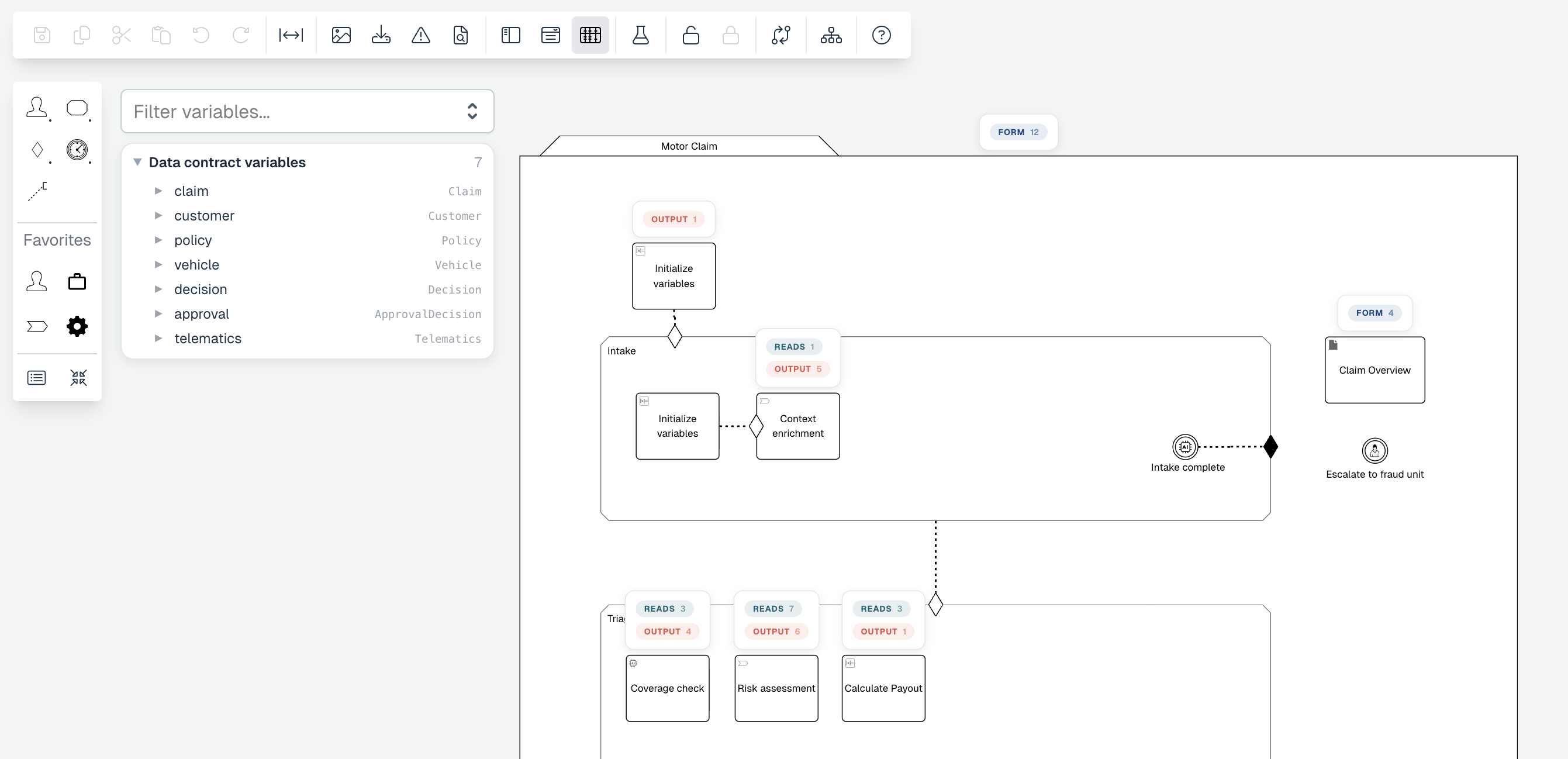
Variable View
Toggle the Variable View with the button to see which variables are created and used across your case. Expand the card above a plan item to see more details about the variables that plan item reads and writes.
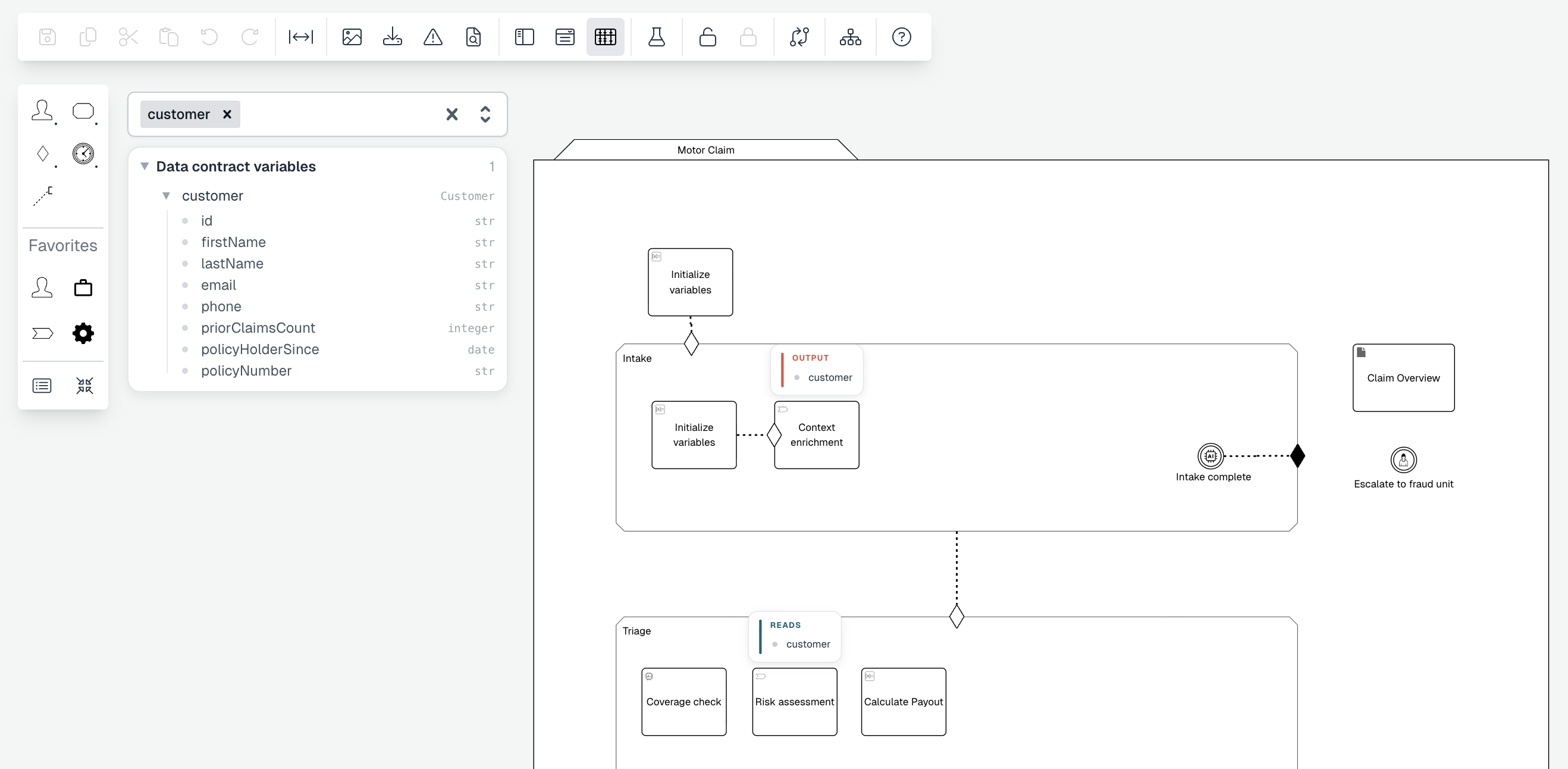
Use the panel to filter by variable name; the diagram then highlights only the plan items that read or write the selected variable.
What is CMMN?
The Case Management Model and Notation (CMMN) is a standard notation and formal specification of the Object Management Group for representing cases. It can be used for capturing work methods that are based on the handling of cases requiring various activities that may be performed in an unpredictable order in response to evolving situations. Using an event-centered approach and the concept of a case file, CMMN expands the boundaries of what can be modeled with BPMN, including less structured work efforts and those driven by knowledge workers. Using a combination of BPMN and CMMN allows users to cover a much broader spectrum of work methods. It provides a standard, common language for all stakeholders, whether technical or non-technical: business analysts, case workers, managers and technical developers, as well as external teams and consultants. Ideally, it bridges the gap between process intention and implementation by providing sufficient detail and clarity into the sequence of business activities.
In addition, CMMN in its current version was designed with automatic execution in mind. This means that a case can be stored as a file and can then be used to automatize case management using a so called CMMN engine such as Flowable.
Purpose of CMMN
CMMN is targeted at participants and other stakeholders involved in case work to gain understanding through an easy-to-understand visual representation of the case model.
Case Plan Model
The Case plan model represents the case itself. It is the top-most parent stage for all model elements of the case.
Attributes
| Group | Attribute | Description |
|---|---|---|
General | ID | A unique ID for the element. The ID is used to refer to a model element from outside of the diagram (for example, from a CMMN Action button in a form or when referring to a model element, such as plan item ID, in a CMMN REST call). For convenience, this ID can be edited. |
Name | The name of the element. This is the name displayed in the diagram. If no run-time name is specified, this name is also used in the running case. | |
Creation date | This defines the date on which the diagram was created. | |
Modification date | This defines the date on which the diagram was last modified. | |
Documentation | Documentation intended to explain concepts of its use for future reference. | |
Security policy | The security policy associated with this element. | |
Folder path for uploaded content items | The folder path where uploaded content items for this case are uploaded. | |
Description | The description attribute additionally adds a description to the component. | |
Details | Version | This defines the version number of the case. |
Author | This holds the name of the author of the case. | |
Initiator variable name | The user that can start the case instance. | |
Target namespace | Target namespace of the case model. This allows you to group models according to your own criteria. | |
Visual | Label expression | Replaces the label of all activities with the provided expression. For instance, |
Font weight | The font weight of the element in the diagram. | |
Font size | The font size of the element in the diagram. | |
Font color | The font color of the element in the diagram. | |
Font style | The font style of the element in the diagram. |
Stages
Stages are used to structure cases. They are often used to represent the different phases of a case or to logically group plan items. It is possible to nest stages.
Attributes
| Group | Attribute | Description |
|---|---|---|
General | ID | A unique ID for the element. The ID is used to refer to a model element from outside of the diagram (for example, from a CMMN Action button in a form or when referring to a model element, such as plan item ID, in a CMMN REST call). For convenience, this ID can be edited. |
Name | The name of the element. This is the name displayed in the diagram. If no run-time name is specified, this name is also used in the running case. | |
Description | The description attribute additionally adds a description to the component. | |
Documentation | Documentation intended to explain concepts of its use for future reference. | |
Details | Required | Select this option to mark the element as required (exclamation mark decorator). Required plan items must either be in the state COMPLETED, TERMINATED or DISABLED for their parent stage to complete. |
Repetition | Select this option to mark the element as repeatable (number sign decorator). By default, only one instance of a plan item is created at runtime. Repeatable plan items do not have that limitation. The combination of this property, Manual activation, and no entry sentry has a special meaning called Automatic repetition: As a previous instance of the plan item completes, a new instance is automatically created and set into state 'Enabled'. | |
Repetition counter variable | The name of the repetition counter variable. | |
Completion neutral | Completion neutral influences the plan item’s parent stage completes. Plan items in the state AVAILABLE may prevent the parent stage (or case) from automatically completing. By checking this property, the plan item behaves neutral with respect to the completion of the parent container. | |
Auto complete | A stage with this option set to true completes more eagerly, even if there are pending non-required children in states 'Available' or 'Enabled'. In other words: With the option set to true, a Stage completes even if it has children in states 'Available' or' Enabled' (unless they are Required). With this option set to false, a Stage only completes if all child elements are one of the states: 'Completed', 'Terminated', or 'Disabled'. | |
Show state | A flag indicating whether the state of this Stage is displayed at run-time. The standard Case template includes a status bar showing the states of Stages and Milestones. When set to true, the Stage is displayed in the status bar with colors reflecting its state: light gray for 'Available'/'Enabled'/'Terminated', red for active, dark gray for 'Completed'. | |
Display order | An integer value (negative, zero or positive) denoting the display order of the Stage’s state indicator relative to other elements in the status bar (see attribute 'Show state'). The smaller the number, the more to the left. | |
Activation | Manual activation | Select this option to mark the element to have Manual activation (right arrow 'play' decorator). Plan items with Manual activation move from state AVAILABLE to state ENABLED once they trigger. A plan item in state ENABLED exposes an action button that allows the user to start the plan item manually. |
More | Lifecycle listeners | It allows you to define lifecycle listeners for a plan item. Lifecycle listeners allow you to execute an expression, a delegate expression or a class when a plan item transitions from one state to another. |
Visual | Font weight | The font weight of the element in the diagram. |
Font size | The font size of the element in the diagram. | |
Font color | The font color of the element in the diagram. | |
Font style | The font style of the element in the diagram. | |
Background color | The background color of the element in the diagram. | |
Border color | The border color of the element in the diagram. |
Tasks
In essence, tasks are the elements that do something in a case. There are a number of predefined tasks:
- Human Task
- Case Task
- Process Task
- Untyped Task
- Service Task
- Script Task
- Decision Task
- HTTP Task
- Flowable Work Activities